Creating wall recesses
|
Command |
Workspace: Path |
|
Create Wall Recess |
Architect: AEC Landmark: Landmark > Architectural Spotlight: Spotlight > Architectural |
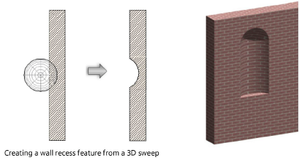
To create a wall recess:
Create the closed 2D or 3D solid object with which to modify the wall. The geometry of the object must define an area or volume that has no self-contacts, no self-intersections, and no edges that fold back on themselves.
For a 2D object, simply make sure that the object overlaps the wall in Top/Plan view. For a 3D object, first create the object at the appropriate height in relation to the bottom of the wall (Z axis); then set the appropriate X and Y axis location so that the object overlaps the wall.
With both the appropriate wall and the modifier object selected, select the command.
Alternatively, for 2D objects only, select Modify > Clip Surface.
The Create Wall Feature Recess dialog box opens; different fields display depending on whether a 2D or 3D modifier object is selected.
Click to show/hide the parameters.Click to show/hide the parameters.
|
Parameter |
Description |
|
Left Side Wrap (2D objects only) |
Select the first component to wrap around the feature on the left side of the wall; this can be <None>, or any component to the left of the Feature Component (higher in the list). All components to the outside of the Left Side Wrap component also wrap. |
|
Right Side Wrap (2D objects only) |
Select the first component to wrap around the feature on the right side of the wall; this can be <None>, or any component to the right of the Feature Component (lower in the list). All components to the outside of the Right Side Wrap component also wrap. |
|
Offset From Wall Top (2D objects only) |
Specifies the distance from the top of the wall where the wall feature ends in 3D views |
|
Cut Plane (3D objects only) |
Specifies the distance from the bottom of the wall at which a section slice is taken of the 3D object and is used to represent the wall feature in Top/Plan view. When the design layer cut plane is enabled (see Setting design layer properties, Vectorworks Architect required), the elevation of the wall feature cut plane is set to the same value as that of the design layer, ensuring a uniform cut plane appearance for the layer. When the design layer cut plane is disabled, or for the Vectorworks Spotlight or Landmark products, specify a cut plane elevation for the wall feature. If the 3D object does not run the whole height of the wall, be sure that this value actually intersects the 3D object; otherwise the object will not appear in Top/Plan view. |
|
Preview |
Changes the view of the wall feature to match the current parameter settings, without saving the settings |